Explain systems and solve computing problems. The 30 quick questions support recall and application; practise full algorithms, programs and evaluations using the PLC tasks.
Revise the key ideas
Gates and truth values
Boolean values — Boolean logic uses true and false, often represented as 1 and 0. These denote truth states in a logic problem rather than arbitrary counts. A truth table enumerates input combinations and the resulting output so the whole expression can be checked.
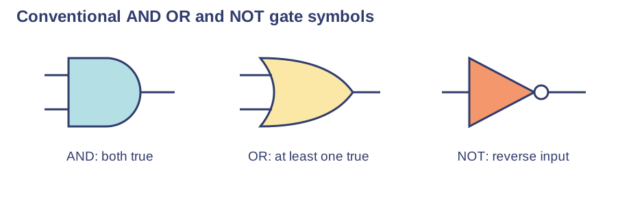
NOT gate — NOT A is 1 when A is 0, and 0 when A is 1. NOT has one input. Negation reverses a Boolean condition, not the digits of a multi-digit number or the order of a string.
AND gate — For A AND B, input rows 00, 01, 10, 11 produce outputs 0, 0, 0, 1. A door rule requiring a valid card and an active account can use AND. Either requirement failing makes the combined condition false.
OR gate — For A OR B, rows 00, 01, 10, 11 produce 0, 1, 1, 1. This is inclusive OR: both true still gives true. Do not interpret it as 'one or the other but never both'.
Gate diagrams — Conventional symbols distinguish AND, OR and NOT; NOT has a small inversion circle. Label inputs and output and follow the wire direction. Two wires crossing are not necessarily joined unless the diagram indicates a connection.Use the labels alongside the associated explanation.
Building truth tables — For two inputs use four rows; for three use eight. A systematic order such as 000, 001, 010, 011, 100, 101, 110, 111 avoids omissions. In general n independent Boolean inputs have 2ⁿ combinations.
Intermediate columns — For Q = (A OR B) AND NOT C, add columns A OR B and NOT C before calculating Q. With A=0, B=1, C=1, those columns are 1 and 0, so Q=0. Trace the expression as written rather than treating every operator as AND.
Expressions and circuits
Parentheses and scope — NOT (A AND B) differs from (NOT A) AND B. For A=1 and B=0, the first gives 1 and the second gives 0. Parentheses avoid ambiguity and help map the expression to circuit stages.
From expression to circuit — For Q = (A OR B) AND NOT C, feed A and B into OR, C into NOT, then both results into AND. The order reflects dependencies. Do not feed the original C directly into the final gate when the expression needs NOT C.
From circuit to expression — If X = A AND B and output Q = X OR C, substitute X to get Q = (A AND B) OR C. Brackets preserve the first gate's grouping. Follow actual connections rather than inferring the result from the symbol nearest the output alone.
Worked compound table — For Q = (A OR B) AND NOT C, outputs in row order 000 through 111 are 0, 0, 1, 0, 1, 0, 1, 0. C=1 always blocks the output; with C=0, at least one of A or B must be 1.
Contextual rules — An alarm that triggers when a window or door is open while monitoring is enabled can use (windowOpen OR doorOpen) AND enabled. Explain each Boolean input. If the requirement changes, the expression must change too; labels alone do not determine the intended rule.
Equivalent expressions — Expressions are equivalent only if outputs agree for every possible input combination. One matching example cannot establish equivalence. You can use complete tables to verify a proposed simplification, even when symbolic simplification is not required.
Program conditions — A validation condition can accept values when value >= 0 AND value <= 100. Rejection can test value < 0 OR value > 100. Using AND between the two outside-range comparisons would fail because one value cannot be both below 0 and above 100.
Checking a logic solution — Draw a circuit, write its expression and produce its truth table, then test the intended scenario. Check that NOT applies to the correct input and that each row appears once. The short questions support gate knowledge; constructing the full representation needs practice.
Test yourself
30 questions · Random sets of 10. These quick checks support revision; practise longer explanations and justified judgements too.
Mind map
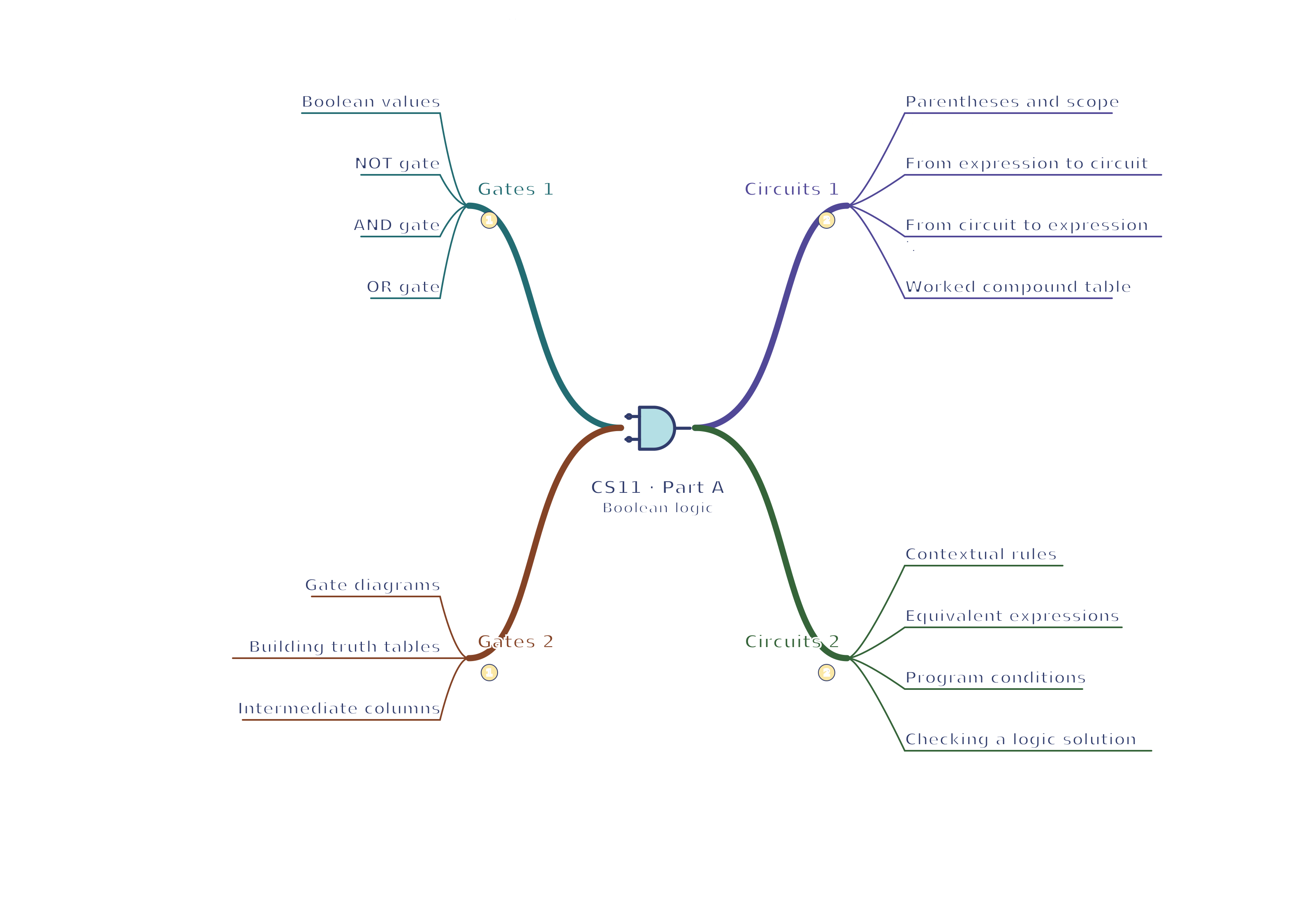
Use the branches to recall the ideas and explain their connections. Check the revision notes for the full detail.
 Mr Kidman's Classroom