SP5 · Light and the electromagnetic spectrumTopic 5 — Light and the electromagnetic spectrum
Electromagnetic waves, uses and hazards
Revise the key ideas
The continuous electromagnetic spectrum
All electromagnetic waves are transverse. They transfer energy, need no material to travel through (no medium), and travel at the same speed in a vacuum: c ≈ 3 × 10⁸ m/s.
The order from longest wavelength/lowest frequency to shortest wavelength/highest frequency is radio, microwaves, infrared, visible, ultraviolet, X-rays, gamma rays.The spectrum is continuous; these bands have no gaps between them.
The spectrum is continuous; the named groups are useful divisions, not gaps where no radiation exists. Human eyes detect only the visible band.
Visible colours from longer to shorter wavelength are red, orange, yellow, green, blue, indigo and violet. Violet has a higher frequency than red.
For electromagnetic waves, c = fλ in a vacuum. As frequency increases, wavelength decreases. Convert wavelength into metres before calculating.
The energy of an individual photon increases with frequency. Total energy transferred by a beam also depends on intensity and exposure time; frequency alone does not determine total energy.
Different wavelengths interact differently with materials: they may be absorbed, transmitted, reflected or refracted. A material transparent to visible light need not transmit ultraviolet or infrared.
Refraction in glass: core practical
Light travels more slowly in glass than in air. A ray entering glass at an angle to the normal bends towards the normal. It bends away from the normal when it returns to air.
Place a rectangular glass block on paper and draw around it. Shine a narrow ray from a ray box onto a face, marking the incoming and outgoing ray positions.
Remove the block and join the marks to trace the ray through it. Draw normals perpendicular to the entry and exit faces; measure incident and refracted angles with a protractor.
Repeat with different incident angles. Keep the block and ray alignment consistent; use sharp pencil marks and widely separated points to reduce direction-reading uncertainty.
A ray entering along the normal (normal incidence) continues straight, although its speed and wavelength change. Its frequency stays the same at both boundaries.
Through parallel-sided glass in air, the emerging ray is parallel to the incident ray but displaced sideways. The two refractions change direction in opposite senses.The ray slows on entering glass; the frequency stays fixed.
Use a ray box, not a laser aimed towards eyes. A beam does not need to be intensely bright to produce clear measurements.
Discovering invisible radiation
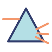
Herschel separated sunlight with a prism and placed thermometers in different colours and just beyond the red end. Temperature increased in the visible spectrum and rose further beyond red.Thermometers also warmed within the visible spectrum.
The warming beyond visible red showed there was invisible radiation there: infrared. It was not the case that visible colours caused no warming.
Ritter investigated beyond violet using silver chloride, which darkens on exposure to radiation. Strong darkening beyond the visible violet region provided evidence of ultraviolet.A chemical detector revealed radiation eyes could not see.
Compare detectors suited to the radiation: eyes detect visible light, thermometers detect heating, and chemical/photographic materials can record radiation effects.
Longer wavelengths: uses and production
Radio waves are used for radio and television broadcasting and communication. Charges vibrating back and forth (oscillating) in a transmitting circuit produce them. When an aerial receives the waves, they produce a changing electrical signal in it.
The transmitted frequency is linked to the oscillation frequency of the charges. Information can be carried by variations in the radio signal.
Microwaves are used in communication, including satellite links and some mobile/Wi-Fi systems, and in microwave ovens where absorption heats food.
Infrared is used for heating, cooking, remote controls and thermal imaging. A thermal camera detects emitted infrared to show temperature patterns; it does not make infrared visible to unaided eyes.
Warm objects emit infrared. Passive infrared motion detectors respond to changing infrared patterns, for example from a person moving through a monitored area.
The atmosphere transmits much visible light and some radio/microwave/infrared bands but absorbs others. Many ultraviolet, X-ray and gamma-ray observations require space-based telescopes; high, dry locations help some infrared observations.
Shorter wavelengths: uses and risks
Visible light enables vision, photography and illumination; very intense light can damage the eyes. Never look into the Sun or powerful beams.
Ultraviolet can cause fluorescence for security marks and banknote checks, and can disinfect water. UV exposure can damage skin and eyes and increase skin-cancer risk; tanning is not a risk-free use.
X-rays form medical and security images because different materials absorb them differently. Dense bone absorbs more X-rays than soft tissue, creating contrast on a detector.Image brightness depends on detector processing; the absorption difference creates contrast.
Gamma radiation can be used with radioactive tracers for imaging and to sterilise medical equipment. Penetration is useful but requires shielding and controlled exposure.
Ionising radiation can remove electrons and damage cells or DNA; X-rays and gamma rays are ionising. UV can also damage DNA; hazard increases with radiation type, dose and exposure.
Microwaves can heat internal tissues, infrared can cause burns and sufficiently intense radio-frequency radiation can also cause heating. Non-ionising does not mean harmless at every intensity.
Reduce unnecessary exposure using appropriate shielding, distance and exposure time. Medical uses balance benefit against risk; the appropriate radiation depends on the task.
Reflection, colour and total internal reflection
For reflection, angle of incidence = angle of reflection; measure both from the normal. A smooth surface reflects rays in an orderly way and can form an image (specular reflection). A rough surface scatters them in different directions (diffuse reflection). Each ray still obeys the same reflection rule at the point where it meets the surface.
A coloured opaque surface absorbs some wavelengths and reflects others. A red surface under white light mainly reflects red; under blue light it may look dark because little blue is reflected.
A colour filter transmits selected wavelengths and absorbs much of the rest. A red filter transmits red light; a red filter followed by a blue filter can give very little transmitted light if their transmission bands do not overlap.
When light enters a material where it travels faster, for example from glass into air, it bends away from the normal. This is movement from a higher refractive index to a lower one. At the critical angle, the refracted ray travels along the boundary.
Total internal reflection happens when light travels from a higher refractive index to a lower one, such as glass to air, and the angle of incidence is greater than the critical angle. All the light is reflected back into the original material. Optical fibres use this to guide light.The incident and reflected rays remain in the higher-index material.
Converging and diverging lenses
A converging lens is thicker in the middle and brings rays initially parallel to its principal axis towards a focus. A diverging lens is thinner in the middle and spreads them as though they came from a focus on the incident side.
Lens power in dioptres = 1 ÷ focal length in metres. A shorter focal length means a more powerful lens: it bends light more strongly. Converging lenses have positive power; diverging lenses have negative power.
In a ray diagram for a converging lens, a ray parallel to the axis passes through the far focus, and a ray through the optical centre continues approximately straight. Their intersection locates a real image.The intersection of the emerging rays gives the inverted real image; drawing is schematic.
A converging lens forms a real, upside-down (inverted) image when the object is beyond the focal point. Beyond twice the focal length, the image is smaller (diminished). Between one and two focal lengths it is larger (magnified). At twice the focal length, it is the same size as the object.
For an object inside a converging lens’s focal length, extend the emerging rays backwards: the image is virtual, upright and magnified on the object side, as in a magnifying glass.
A diverging lens gives an upright, diminished virtual image for a real object. A virtual image is located by backward extensions of rays; it cannot be projected directly onto a screen as a real image can.
Draw a labelled principal axis, lens, focus points and object, then use straight rays with arrow directions. Use dashed lines for backward extensions rather than treating them as real rays travelling backwards.
Thermal radiation and temperature
All bodies emit electromagnetic radiation. As temperature increases, the emitted power generally rises and the distribution shifts towards shorter wavelengths; hot enough objects can emit visible light.
(Higher tier) A body at constant temperature absorbs energy at the same average rate as it emits it (Higher tier). If absorbed power exceeds emitted power it warms; if emitted power exceeds absorbed power it cools, until the balance changes.
(Higher tier) Earth’s temperature depends on the balance of incoming solar radiation, reflected radiation and outgoing radiation. Greenhouse gases absorb and re-emit some outgoing infrared, affecting the balance (Higher tier); reflected sunlight and absorbed energy are different parts of the balance.
Dark, matt surfaces are generally better absorbers and emitters of thermal radiation than shiny, light surfaces under comparable conditions. Good emission and absorption tend to accompany one another.
For the core practical, compare at least four otherwise similar containers with different colours or shiny/dull surfaces. Put equal volumes of hot water at the same initial temperature into them and use lids; record temperature at fixed intervals.Compare temperature changes with the same apparatus and exposure conditions.
Keep container material and size, water volume, thermometer position and room conditions consistent; compare cooling curves and repeat. Faster cooling can indicate stronger radiation, but conduction and convection also affect the experiment and must be considered.
To compare absorption, put otherwise identical surfaces the same distance from the same radiation source. Keep starting temperature and exposure time the same. Use the same material so a change caused by colour or texture is not confused with one caused by different materials.
Watch SP5 · Light and the electromagnetic spectrum · Topic 5 — Light and the electromagnetic spectrum
Revise light and the electromagnetic spectrum with this narrated video. Use the player controls to pause, seek, adjust the volume or mute. Turn English captions on or off using the captions menu.
 Mr Kidman's Classroom